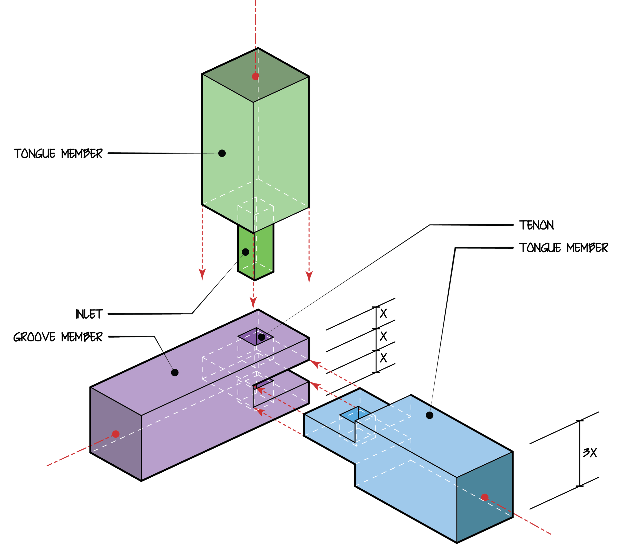
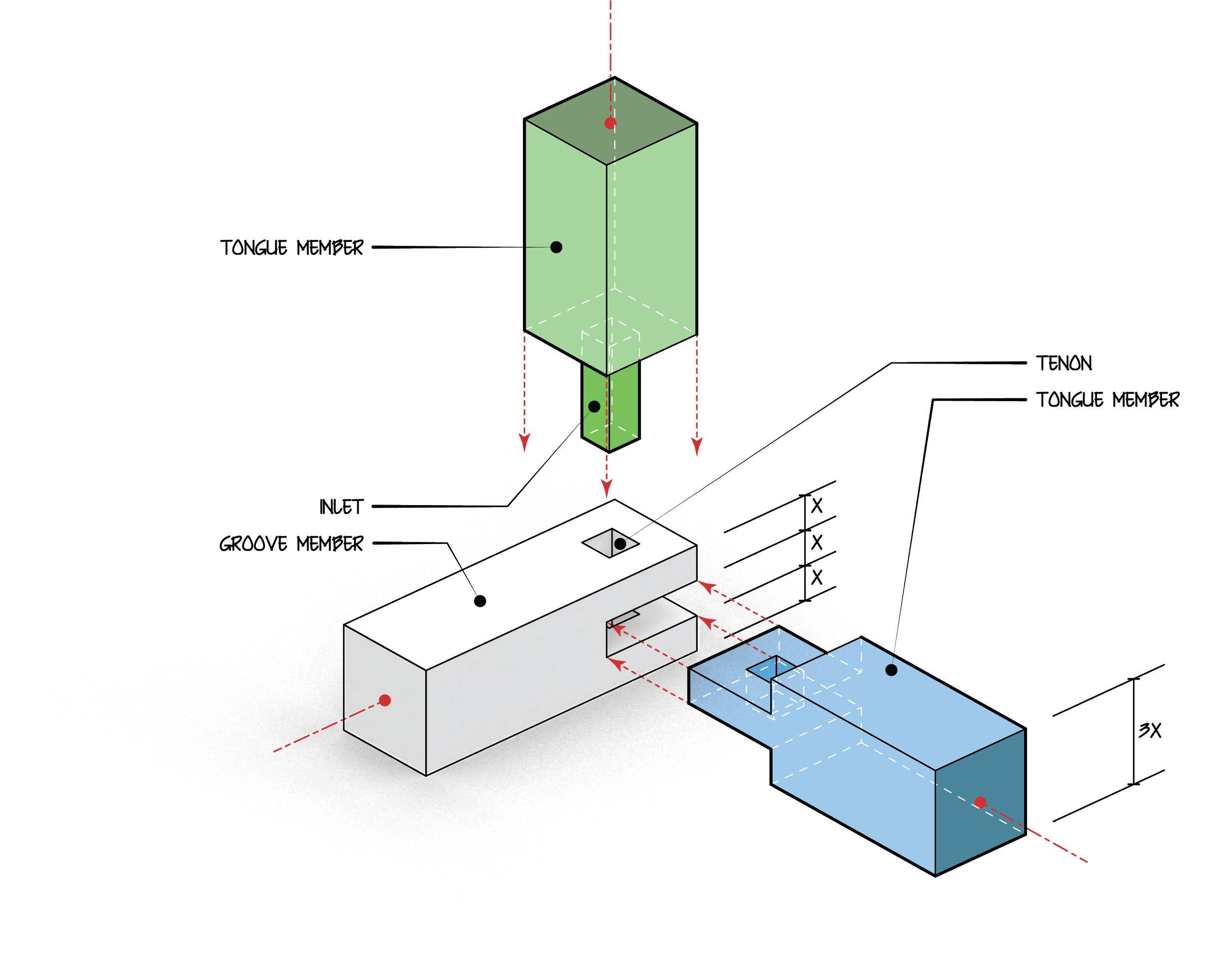
Exploded Axonometric
Workflow Tutorial
Bridle Joint with Inlaid Through Tenon Example
Rhino 3D → Illustrator → InDesign
Rhino Modeling Workflow
Before you model (do not skip)
Goal: make geometry that can become a clear exploded axonometric drawing.
Set correct units (mm or inches) before modeling.
Model each part as a separate solid (do NOT fuse everything).
Name and organize parts using layers.
If you cannot select and move parts independently, your exploded axon will fail
01 | Prep Rhino File
This tutorial works with any system - but the files are set up in the metric system (centimeters).
Turn on Gridsnap, Gumball, Osnap (end, mid, int, perp, and point)
Setup Layers
00_Workline | to use for work-in-progress objects
10_Groove | for Groove 3D member
10_Tongue | for Tongue 3D member
10_Inlet | for Inlet 3D member
20_Make2D | for 2D projection layers & sublayers
30_Annotations lines
30_Leading Lines
Set up Exploded Axon View Port
Choose ViewPort > Set View > Isometric > SE
Adjust View
Choose ViewPort > Set View > Named Views > Save As
to update - repeat
Milestone 01 — Clean Rhino Setup EA_01_Layers_Setup.3dm
Hints & Tips:
Keep layer Numeric prefixes improve sort order. Clear distinction between timber and annotation layers helps with Make2D output after export.
Adjust the Isometric view using the Orbit and Zoom tools to avoid overlapping lines
If the view is bumped, double-click the saved Named View to restore it.
Do NOT click the viewport title and switch to Perspective. If you need both Perspective and Parallel, use 2 different viewports.
If the viewport title says Perspective, stop and switch to Parallel immediately.
02 | Basic Timber Members
Build 2D profiles of Tongue and Groove Members. Make sure they are polylines
Through tracing with Polyline
Or Join segments
ExtrudeCrv > Solid
If extrusion is still not solid, use the Cap command
Build the Inlet member directly in 3D
Trim the surface to open the solid to receive the Inlet
trace opening with a polyline
ExtrudeCrv in Plan view
Select Member an Inlet > Boolean > Union
Milestone 02 — Basic Timber Members EA_02_Basic_Timber_Model.3dm
Hints & Tips:
Select polylines after joining to make sure all segments are included in the profile
If unsuccessful, that means some lines are not intersecting - use the extend command to make sure lines are intersecting.
Select the 3D Inlet object after the Boolean command to make sure the member is it is one object
If unsuccessful, turn on Osnap>End and use a move command to move from end point to end point to make sure the edges align
03 | Joint Cuts and Member Fit
Before you start, make a copy of the members and move out of Exploded Axon View
Before you rotate, turn on Ortho
Use GumBall to rotate in Top, Front, and Perspective (or Right) views to assemble objects.
Use BooleanDifference to subtract the Inlet member from both the Tongue and Groove members.
DeleteInputs = Yes, Delete Cutters = No
Milestone 03 — Joint Geometry Complete EA_03_Joint_Cut_Complete.3dm
Hints & Tips:
You can hold shift to temporarily step into Ortho Mode, BUT, if your ortho is already on, this will turn off Ortho.
After BooleanDifference, turn the Layers on and off to ensure cutting is successful.
04 | Exploded Axon Setup
Before you start, make a copy of the assembled members and move out of Exploded Axon View
Use Gumball in the top, front, and right views to pull apart the members along clear axes
Adjust Exploded Axon View and resave - if needed
Optional: add light guide lines on a separate layer. Can also be added after the Make2D step - before exporting to Illustrator
Milestone 04 — Exploded Axon Setup EA_04_Exploded_Axon_Setup.3dm
Hints & Tips:
Use the grid to line up objects to keep explode distances consistent
Make sure objects are not overlapping in Exploded Axon View
If the file is omnidirectional, you can mirror the assembly for a clear view
05 | Make2D Output
Before you start, make sure the Exploded Axon view was not bumped or changed to perspective. If the view is perspective, your Make2D will be incorrect.
Select exploded parts and use the Make2D command.
Settings to use:
View: Exploded Axon
Projection: View
Object Properties > Maintain source layers: ON
Tangent edges: OFF (for timber details)
Hidden lines: ON
Scene silhouette: ON
Viewport Rectangle: ON
Layer name: 20_Make2D
(layer previously created)
Before you export - add Annotation lines + fill layers
Add lines that will be arrows in Illustrator
Copy Sillhoette Sublayer > Duplicate layer and Objects
When asked to duplicate sublayers > Yes to All
Right-click each layer > Select Object > Join
Add leading lines for dimensions and annotations
Once the lines are ready for export:
Select all 2D lines: File > Export >Save as type> Adobe Illustrator (*.ai)
Before you press Save! Select Options
Preserve Model Scale 1cm = 1cm
Choose CMYK to make sure colors print as intended
Milestone 05 — Make2D Output EA_05_Make2D_Output.3dm and EA_05_Make2D_Output.ai
Hints & Tips:
The viewport Rectangle usually is a rectangle and changes the aspect ratio when exported to Illustrator - add a square frame instead. Add a square around it to ensure the aspect ratio travels well.
This rectangle serves as a guide if you need to go back to Rhino mid-Illustrator process to add more objects.
Output curves should land on sublayers under the layer you created, namely
20_MAKE2D.Dimension lines do not travel well from Rhino to Illustrator - need to be built manually.
Adjust leading lines to line up with each other and receive text.
06 | Prep Illustrator File
Adjust Artboard > Landscape
Setup Layers
01_Silhouette Curves
02_Silhouette Fill
03_Visible Curves
04_Cut Edges
05_Hidden
06_ViewportRectangle (untick Print)
07_Annotations lines
08_Leading Lines
09_Text
Lineweight Selection Rules:
Silhouette:Visible:Interior: Hidden
4 : 2: 1: 1 (dashed)Use Hierarchy, Not Variety. Limit yourself to a maximum of 4 lineweight categories.
Text Size:
Reading: 11-12 pt
Poster: 24-36 pt
Milestone 06 — Illustrator Base File EA_06_Illustrator_Base.ai
Hints & Tips
The geometry will land in relationship to the Rhino origin
Select All and move corner to x = 0 and y = 0
Scale all to fit on Artboard
The orientation of the Artboard should be mediated by the design - Not everything needs to be in Landscape
General Architectural Fonts:
Arial
Century Gothic
If you need more than four lineweight categories, your model is too complex, or your drawing lacks clarity.
Use the Distance test to check lineweights and text size; i.e., Print preview at 25% scale or zoom out.
The lineweight hierarchy and text hierarchy should align. Match the silhouette typographic weight with the graphic weight.
Poshe colors:
Body: Brightness
Focus: Fully Saturated
Cut Surfaces: Desaturated
07 | Hybrid Representation (Render + Linework)
Only render the complex geometry - turn off the other layers before rending
Set up Rendering Option: Right-click on Render
Resolution and Quality > Final Quality (1500 Samples)
Background > Transparent Background: ON
Ground Plane > Show shadows only: ON
Render: Left-click on Render
Denoise: ON
Save
File time *.tif or *.png
Transparent: ON
Create a new Layer (10_Image Render)
After importing the rendered image, keep the aspect ratio locked and use the center reference point to tweak the image size.
Tweeks
Move the image layer behind all visible line layers
Turn off the Hidden lines that are associated with this member to avoid information.
Turn off the Poshe layers associated with this member
Milestone 07 — Illustrator Poshe/Render Hybrid EA_06_Illustrator_Poche Alt.ai use EA_07_Rendered_Members.tif
Hint and Tips:
This is the best option for more complicated geometry.
Always make sure the Axon View is reset before rendering
When rendering, stick to simple materials (neutral, no textures).
If you want to blend colors, use blending effects and/or opacity
08 | Layout and Text in InDesign
Prepare InDesign File
Select Sheet Size
Windows > Paragraph Style > Create new Styles
Body
Annotations
SubTitle
Title
File > Document Setup > Page Size + Margins
Create new Layer: 01_Text
Place Images on board - adjust scale and rescale
Lock Images before adding text
Use paragraph styles to ensure that all text across all layouts remains consistent, regardless of scaled drawings.
Milestone 08 — Layout Design EA_08_Layout_Template_v1.0.ai and EA_09_Exploded_Axon_Board.ai
Hint and Tips:
Illustrator is for line discipline - InDesign is for page composition.
Place *.ai files instead of PDF to:
Keeps vector data live, preserves lineweight precision, and maintains a clean workflow across revisions.
Allows updating an Illustrator file without rebuilding the layout.
If you update the .ai file > Save in Illustrator > Return to InDesign > double-click Update Link in the Links panel.
If you get lost in the Paragraph Style options, you can adjust independently and then right-click on Paragraph Style > Redefine Style
Keep scale changes similar & Lock aspect ratio
Avoid the box - layout and use the lines for composition
If you update iA files, the images may shift - readjust the scale
Ultimately, it is better to manage the Illustrator artboards mediated by the InDesign Page size - this ensures:
Everything is placed at 100%
Lineweights will not need adjustment
Text does not need to be adjusted
Developed for ARCH 2020 Studio Spring 2026 | ISUAdaptable for cross-section instruction